Prepare a croft plan
Plans criteria in detail
Scale and surrounding detail
A scale and an orientation of north must be shown. A drawn bar scale is preferred, because it allows distortion from any subsequent photocopying to be identified.
The plan must contain sufficient surrounding established detail, such as fences, houses, road junctions, to enable its position to be fixed with accuracy.
This is illustrated in figures 1 and 2.
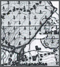
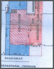
Figure 1:
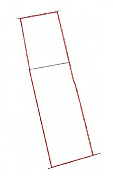
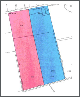
In figure 1 neither the orientation nor scale of the subjects can be determined from the plan nor is it possible to determine what subjects they relate to. This plan could potentially relate to either of the subjects coloured pink and blue on the Ordnance Map. Therefore the plan submitted with the application (‘application plan’) must also contain enough surrounding detail to allow its position to be located and fixed with accuracy.
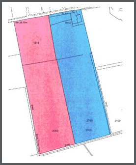
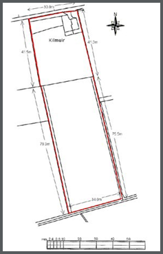
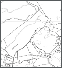
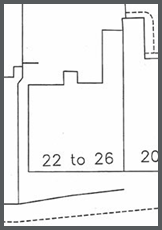
A good illustration of how the plan should look is shown in figure 2. The plan identifies the orientation and sufficient surrounding detail to allow us to identify the subjects as the area blue on the OS map.
Figure 2:
If the scale of the most suitable map is insufficient to reflect the necessary detail, an inset plan at a larger or more detailed scale may be used. Situations will invariably arise when even the 1:1250 scale map cannot provide sufficient detail and plans at a larger scale - for example, 1:500 - may be utilised to identify smaller areas/details, e.g. a resumed area within a large common grazing.
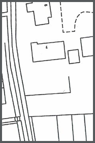
In figure 3 an applicant has used the 1:50,000 scale OS Land Ranger map as the basis for the crofting plan. When comparing the 1:50,000 scale plan used by the applicant with the standard 1:10,000 OS map, used by the keeper, we see that the 1:10,000 OS map shows significantly more detail than that shown on the applicants plan. The lack of detail on the 1:50,000 plan when compared with the 1:10,000 makes it impossible to clearly ascertain which features the legal boundary follows.
In this instance the 1:50,000 plan would be rejected and a new plan showing clearly the extent sought to be registered would need to be prepared prior to re-submitting an application for registration.
Figure 3:
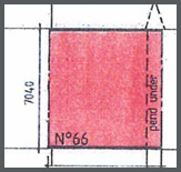
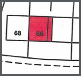
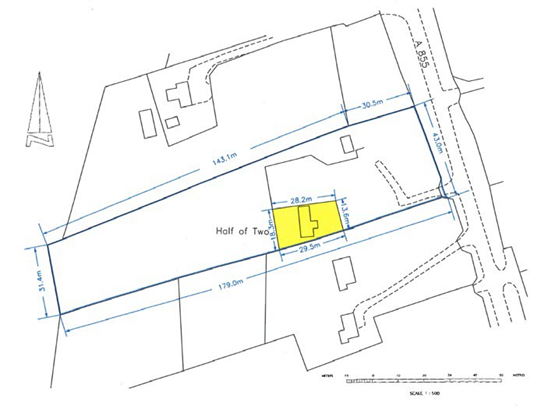
If a plan is submitted at a large scale it may show details such as juts which fall outwith the OS capture criteria for that scale of map. The application plan in figure 4 shows that the fences to the front and rear of the gable wall between numbers 66 and 68 do not project in a straight line from the gable wall, ie they lie slightly to the east of the gable wall. Small juts of this nature are not shown on the OS map. In this instance the subjects would be registered following the boundaries depicted on the OS map.
Figure 4:
The deed plan in figure 5 depicts small juts on the frontage of the building. Juts of this nature would fall outwith current OS data capture tolerance.
Figure 5:
Graphic representation
The land sought to be registered must be clearly indicated by means of suitable graphic references, such as edging, tinting, and hatching.
Figure 6:
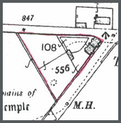
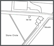
Figure 6 illustrates subjects which have been hand drawn on the plan with a red pen. In this instance it is not possible to ascertain which feature the south west boundary should follow, nor is it possible to accurately identify the boundary in front of the cottages sought to be registered.
Registration events, such as resumptions, decrofted areas requiring a plans reference, must be properly differentiated and referenced and be consistent with the information provided on the application form. Where there is already a plan that exists for decrofted areas etc and it meets our criteria then there is no requirement to show it on the new plan that you are preparing to show the extent of your croft. Figure 7 clearly identifies the decrofted area referred to in the relevant application form attached with this plan. Please note that a croft plan can be supplemented with an existing plan - for example, a plan to an existing de-crofting direction - provided that the existing plan meets our requirements.
Figure 7:
Dimensions
Where measurements are deemed necessary, the dimensions depicted on the plan should agree with the scaled measurements.
Scales and measurements based on the Imperial system, for example 1 inch to 8 feet, or 60 feet, are not acceptable in the preparation of any new plans for submission into the Crofting Register. However, an old plan that uses imperial measurement but otherwise meets our essential criteria for the preparation of plans would be deemed acceptable.
Undefined boundaries, where no physical boundary exists, must be accurately fixed to existing detail by metric measurements shown on the plan.
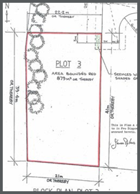
In figure 8 the property shown as plot 3 on the plan has been defined as number 7 on the OS Map. The OS Map does not show a feature between number 7 and its neighbour to the north, number 9. The plan has accurately fixed the undefined south boundary, using dimensions, it has specified that the undefined boundary is 39.4m from the south boundary at its westmost point and 41m at its eastmost point.
Figure 8:
A plan employing dimensions which are simply a perimeter measure and incapable of being accurately plotted or proven is unacceptable.
Dimensioned plans that are not based on OS Mastermap should include proof measurements which may consist of:
- cross/diagonals; or
- angles at each change of boundary direction; or
- local or National Grid co-ordinates of boundary changes supported by appropriately measured and defined dimensions that accord with the coordinate details; or
- any other form of independent check which is capable of proofing the measurements
Ancilliary useful information
Details of how, by whom, and when the plan was completed. Information as to the currency of the survey detail and whether or not it relates to the ‘as built’ positions or merely the proposed layout should also be noted.